
Installing the DITOS Board in older versions of CompIQ Stella Pro Compressor
We have been asked if the DITOS board can be installed in older versions of the CompIQ Stella Pro Compressor, and the answer is actually yes, it can. It involves drilling the enclosure for the output connector and soldering the four interconnection wires on the circuit board. This tutorial will guide you through the steps required for installation.
When you order a DITOS Transformer-Coupled Balanced Output DI Board, please let us know of your CompIQ Stella’s board version or the serial number of the pedal. If the board version is 1 through 1.3 we will prepare the DITOS board interconnection wiring a bit differently from how it comes for the new 1.4 version released in September 2021.
⚠️Disclaimer! You will be solely responsible for the success of the installation. We may provide only limited guidance and support for troubleshooting, and if any damages are incurred we will not be held responsible. The installation should be performed by a skilled technician who understands electronics, wiring diagrams, and signal flow. We cannot and we will not make custom wiring drawings. Hand working and solderings are required. Proper mechanical, electric, and testing tools are needed.
Drilling
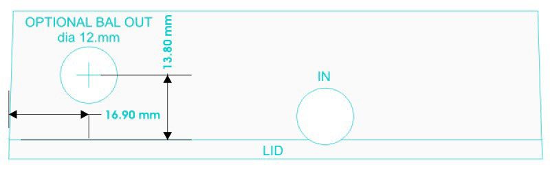
First of all, you will need to drill the enclosure for the balanced output connection. The hole must be 12mm in diameter. We recommend using a quality battery-operated hand drilling tool (like a DeWalt) that can control the speed of the drill, instead of using a drill press that may be too wobbly at high speeds. We advise you to follow these steps:
- Take the knobs off of the potentiometers.
- Use a tubular wrench to remove the nuts that secure the potentiometers (10 mm) and the footswitch (14 mm) to avoid scratching the white markings on the pedal face.
- Wrap some protective waxed paper around the enclosure to avoid scratches on the painting and the white markings on the face when the enclosure is secured in the vice.
- Put the lid back on on the enclosure and secure the enclosure in a vice for drilling.
- First, mark the point where you will perform the drilling with a carbon pencil. Use a precision aluminum ruler to make your measurements. Then use a punching tool to make a dent in the enclosure and be sure the drill won’t slip around.
- Drill a ⌀1 mm diameter guide hole first, then drill the final ⌀12 mm diameter hole. Use the template below. This way you will have the best precision for this operation.
Soldering
We will place the connector on the DITOS board and leave the end of the wires to be soldered by you on the circuit board as depicted in the pictures below. First of all, you will need to isolate the Tip tab on the output connector (which has switching tabs). This is needed so that the output signal from Stella’s mainboard won’t be put to the ground when you take out the jack from the main (VCA) output connector. This is useful if you intend to only use the new transformer balanced output alone. If you don’t isolate this tab you will need to have a jack inserted in the main output connector to keep the Tip tab off the ground. Of course, as soon as you take out the jack, the Tip tab in the connector will spring back to the circuit ground and no signal will flow to the DITOS. See the first image below for a better understanding.
Follow these steps to continue the installation:
- Isolate the Tip tab of the connector with isolation tape.
- Solder the Red (Hot) wire to the Tip tab on the output connector.
- Solder the Black (Ground) wire to the Ground tab on the output connector.
- Solder the Yellow (Vref) wire to pin 1 of the Gain potentiometer.
- Solder the Green (Positive Power) wire to the positive [+] lug of the power filter capacitor – the largest one on the board.
- We advise you to use liquid tape to protect the soldering points of the wires on the mainboard.
- Interconnect the DITOS to Stella’s mainboard. Set the DITOS board in place and secure it with the connector nut. Be sure that the stiff solid wire soldered on the DITOS board is locked tight against the inner side of the chassis for good electrical connection. Wire’s thickness also aligns the board against the tapered walls of the enclosure.
- Use isolation tape to wrap around the battery clip and prevent its tabs to touch anything inside, including the aluminum enclosure.
- Reassemble the pedal.
- For operation, please refer to DITOS & Stella’s manuals.
- Enjoy!


Limitations
Stella’s mainboard in the older versions is not prepared with a jumper for disconnecting the circuit Ground from the enclosure. You will be able to lift the ground from the balanced output connector’s Sleeve (Pin 1 on a corresponding XLR connector) by using the Jumper on the DITOS board. For more details on why this might be needed, please refer to the DITOS manual.


