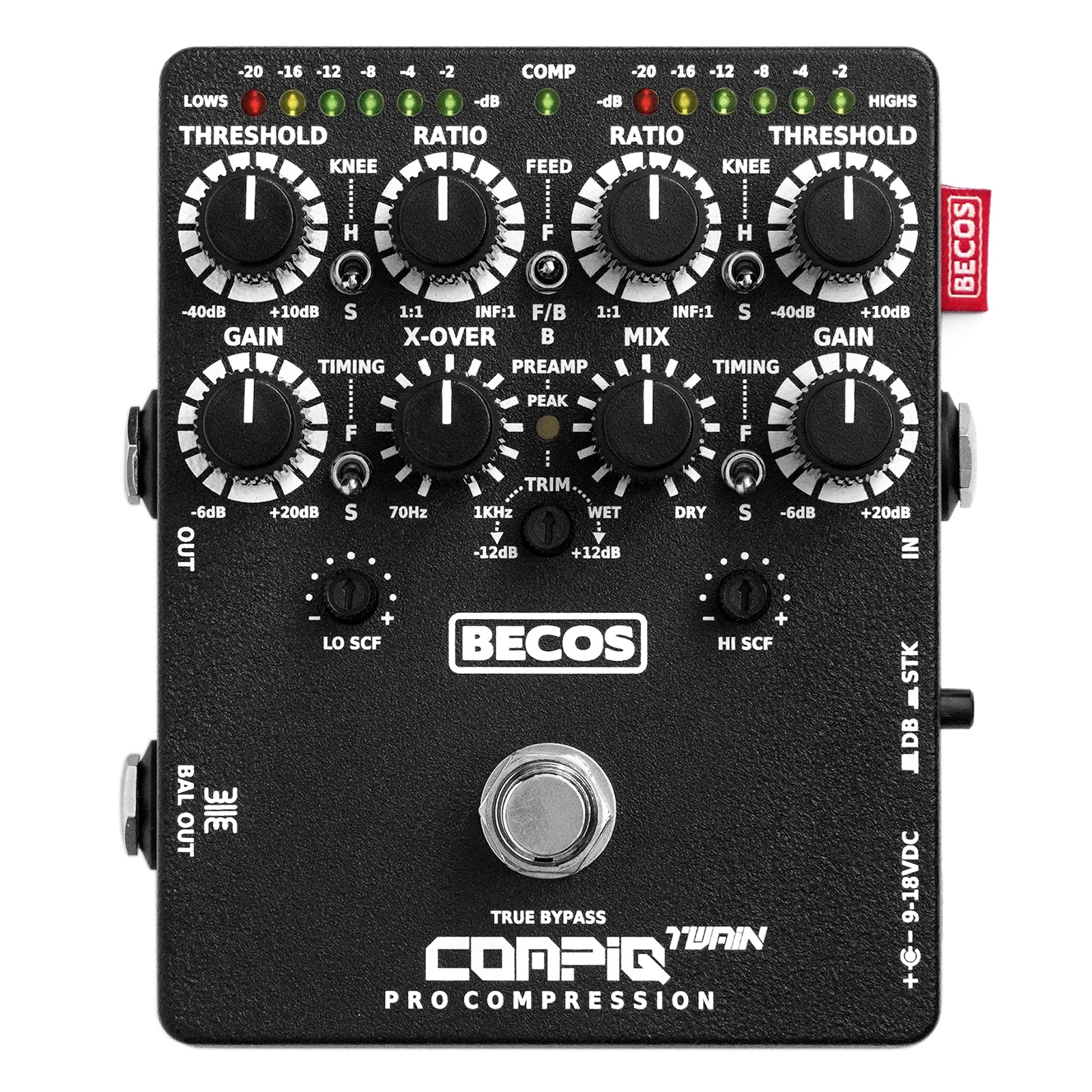
Built around the top-tier 4320 Analog Engine® from THAT Corp. and Texas Instruments Burr-Brown™ FET technology, the CompIQ TWAIN MK2 offers compression parameters that are available on professional studio equipment. In addition to its dual-band processing capabilities, the pedal’s two independent analog engines can be stacked in series to attain the enhanced gluing character typically found in smooth optical compressors.
If you feel like your stompbox compressor doesn’t give you enough control, this could be the answer to your prayers and then some. The Twain is more like a multi-band mastering compressor than the units most guitarists will be familiar with. It’s ideally suited to the twin challenges of wider frequency and dynamic range presented by active basses. A remarkably versatile compressor pedal with a low noise floor and pristine audio quality.
The CompIQ TWAIN offers more than just compression, it includes preamp-like functions to enhance your instrument’s tone without needing a separate EQ. By adjusting the processing levels on each band, you can easily de-balance Lows and Highs around the crossover point and blend Dry over the compressed Wet-line. This technique adds dynamic character while preserving the original tone of the instrument.
The preamp section lets you adjust the input signal level to control how much the compressors engage. Strong signals can trigger compression too early, and the preamp offers up to -12dB of padding. Weaker signals can be boosted by up to +12dB of gain to help with less powerful passive pickups. The preamp works on both Wet and Dry lines simultaneously and can act as a simple one-knob balancer when switching between instruments. A Peak-level indicator signals Green at -2dBu, showing the strength of the input signal, considering the preamp’s amplification or cutting. It turns Red when Twain’s output stages hit +2dBu due to the preamp and make-up gains acting in series. Intermittent Green and Red signals indicate a fairly leveled, cleanly processed signal. If both thresholds are reached simultaneously, the indicator turns Orange. If Orange or Red indication is steady, level readjustments may be needed for an optimal professional line-level signal.
The Twain MK2 offers two selectable compression modes for both Lows and Highs engines, with an additional combination of Feed Forward for Lows and Feed-Back for Highs. Feed Forward mode emphasizes speed and accuracy, using a pre-VCA input signal copy and can range from subtle compression to brick-wall limiting. Feed-Back mode provides a smooth and transparent response for evening out dynamics, using a post-VCA signal copy, and is ideal for low-to-medium compression ratios. Though Feed-Back mode is less suited for hard peak-limiting, it can still act as a genuine soft limiter by adjusting the threshold, using a hard knee, selecting a higher ratio, setting fast timing, and boosting the side chain filter’s control signal. Both modes sound clean and natural, free from pumping, breathing, distortion, or other artifacts.
Additional improved features are have been introduced for the side-chain processing. A variable Lo-cut/boost filter (±12dB @ 70Hz, 12dB/octave) is available on the Lows engine. This filter prevents high-amplitude low frequencies from touching the threshold too early, which can cause over-compression of the upper-frequency elements. Cutting lows in the side-chain reduces compression in the lows at the output, naturally restoring overall signal energy. Conversely, boosting lows in the side-chain helps increasing compressor sensitivity for lower-level signals. A matching variable Hi-cut/boost filter (±9dB @ 3kHz, 12dB/octave) on the Highs side-chain engine further refines this balance. Cutting highs in the side-chain prevents their over-compression, maintaining natural audio brightness at the output, while boosting highs in the side-chain increases Highs compressor’s sensitivity to these frequencies, which helps with over-bright instruments. When both Side Chain Filters are set to cutting, the compressor remains more sensitive to mid-frequencies, resulting in more compression in this range. With filter knobs set at noon, the side chain processing uses the full-frequency range signal derived from the input. These advanced features help manage compression across lows, mids, and highs, providing dynamic impact without unwanted pumping and maintaining general audio balance.
The CompIQ TWAIN offers independent controls for Hard/Soft Compression Knee, a 50dB Threshold range for instruments and line-level sources, continuous Ratio selection from 1:1 to limiting, and up to +20dB of Make-up Gain.
The inclusion of Dynamic Auto Timing (Fast / Slower presets) for both bands reduces setup complexity of a dual-band compressor and provides a musical response that is suitable for virtually any musical application.
The DITOS Transformer-Coupled Balanced Output DI is an optional feature that uses ultra-quiet FET Burr-Brown™ technology and advanced line drivers for high performance, signal conditioning, and a warm, musical tone. The 1/4″ TRS output supports direct recording, connection to a mixing console, or acts as an unbalanced floating output with a 1/4″ TS mono plug for linking to another pedal or amplifier. It includes an internal ground-lift jumper to resolve ground-loop noise; we recommend leaving the jumper on unless internal circuit ground lift is needed. When the main VCA output is in true bypass, DITOS still receives input from it, functioning as a consecutive device. Twain and DITOS share active components, even without the DITOS balanced output installed. This always-connected active load results in a slight signal level difference between Twain’s powered and non-powered VCA output true bypass. When not powered, the DITOS can’t output any signal.

Note! The DITOS marking is present on all enclosures, even if the DITOS option isn’t purchased, to streamline production. If you’d like to add DITOS later, the pedal must be sent to us, with prepaid installation and return shipping costs. Contact us for details on adding DITOS to your Twain.
Hear the sound on bass
Sound samples courtesy of Victor Brodén who wrote an in-depth Twain MK1 review in the Premier Guitar October 2020 Pedal Issue, p.116. The first take in each track is with the pedal in bypass, followed by another one with compression engaged. Details about the pedal settings for each recording can be found in the Twain MK1 Settings Examples.
Whatever bass style you’re playing, the Twain can put you in total control. Then there’s the fact that the Twain can accommodate line-level signals: this and the pristine signal path make it suitable for use as a studio processor.
The engineering feat is admirable. The number of features make this compressor hard to beat. The Becos shines in the heavier settings — compressing like some of the legendary rack units.
It’s amazing how many options Becos FX has put in these boxes. I am not aware of any analog devices that offer a similar range of functions and, despite the numerous possibilities, they can be set quite intuitively.
If you are into compression, the Becos CompIQ Twain Pro Compressor is in a league of its own. The ability to run it in dual band mode or a stacked mode is killer. Though the Twain is a VCA based device, stacked mode makes the device feel and react more like an optical compressor, which it does well.
For any player that wants absolute precise control over their compression, this pedal should be perfect. In line with its predecessors in the CompIQ range, the face of the TWAIN is jam-packed with controls to manage your dynamics.
The new CompIQ TWAIN takes things further. I dare say it may be a little much for some – but it has some amazing possibilities that I’ve not seen in another pedal format. If you are into compression – then this will give you more control than any other comparable pedal-based unit. Becos have steadily been building up a stellar reputation in this field.
Dual-band/stacked effect boasts two independent analog engines, controls for knee, threshold, ratio and make-up gain and much, much more.
Pristine audio processing
The CompIQ series of compressors preserves the unique tonal characteristics of the input signal. They provide pristine audio compression and offer a high dynamic range, which enables clean, natural-sounding tones with minimal noise and no artifacts or distortions in any settings.
Key features
- Functions as Dual-Band compressor or Stacking compressors in series
- Two independent 4320 THAT Analog Engines® with RMS-level sensors coupled with high-performance Blackmer® VCA’s
- Optional DITOS transformer-coupled balanced output (10KΩ impedance, +6dB default gain; can function as floating unbalanced output as well)
- Input Preamp with trimming for -12dB of attenuation and up to +12dB of gain
- Peak level indicator for signals above -2dBu at input preamp and +2dBu at final output buffer
- Variable 70Hz to 1KHz Linkwitz–Riley Crossover
- Independent Ratio, Threshold, and Make-up Gain
- Independent Compression Knee (Soft/Hard)
- Independent Dynamic Auto Timing presets (Auto Fast / Auto Slower)
- Selectable Feed Forward / Feed-Back / Combined compression mode
- Side Chain Frequency Compensation for balancing the triggering potential of Lows & Highs – equivalent to a frequency-based progressive threshold
- Side Chain Filters with cut & boost function on Lows and Highs engines
- Dry / Wet Mix knob for parallel compression in either of the working modes
- 6-LED gain reduction display on each band
- True Bypass on/off footswitch
- 9-18V DC external power supply (not included), center negative, 12mm long barrel plug
- Road-ready, durable, black-powdered aluminum enclosure (Hammond)
- 3-years warranty (direct to manufacturer, international, transferable)
- Hand-assembled in Vienna, Austria
Reviews
For more reviews, mentions, and information, please visit our Blog.

Posted: May 7, 2020
Designed for both bass and guitar, this squeezer can operate in dual-band or stacked mode, features two independent 4320 THAT analog engines, and includes tape saturation emulation.

Posted: December 4, 2020
We are happy to see the CompIQ Twain receiving the “Recommended Gear of the Year 2020” badge in the Guitar Magazine “Best guitar effects pedal of 2020” awards!
Posted: March 22, 2020
The Twain cooks up every style of guitar compression we can think of – from subtle and transparent detail enhancement through Lowell George and onto brickwall limiting with unlimited sustain.

Posted: March 6, 2020
We advise you to explore the settings one by one, to hear their action. Sometimes small adjustments on pairs of controls can make a big difference.

Posted: November 8, 2021
The CompIQ TWAIN was nominated for the Sound On Sound Awards 2022 in the Guitar Technology Product category. If you like our products please vote for the CompIQ TWAIN before midnight 30 November 2021.
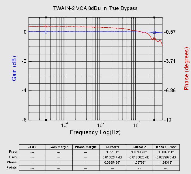
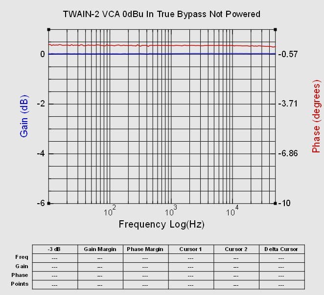
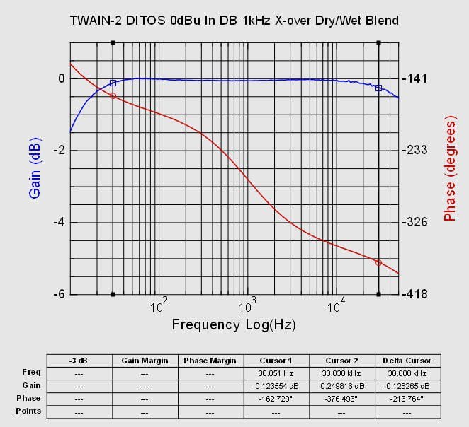
The measurements were taken using FRA4PicoScope 64-bit software with a PicoScope 2204A oscilloscope and its synchronized signal generator, a 0dBu (2.19Vp-p) input signal positioned between instrument-level dynamics and near pro line level, and a 9VDC power supply. The CompIQ Twain Dual-Band / Stacked Pro Compressor MK2 controls were set to balance input and output levels across the Dry and Wet lines in Dual-Band processing mode, covering both Effect and Bypass. The DITOS active transformer DI follows the VCA output in series, as if using two consecutive pedals. While the VCA output can be truly bypassed, the following DITOS stage is active, so the VCA’s signal, whether effect or bypassed, always routes through the DITOS transformer. Each output was connected to a high-impedance load during measurement.
VCA output, true bypass (1)

DITOS output, with compressor bypassed
VCA output, 100% Wet line
DITOS output, 100% Wet line
VCA output, 100% Dry line (2)
DITOS output, 100% Dry line (2)
VCA output, true bypass, pedal not powered (1)
DITOS output, with blended Dry/Wet lines (2)
Note 1: While powered and in true bypass, the VCA output has the DITOS active DI as a connected load, causing a slight phase bend averaging a mere 1.3° around 10kHz and above, with no frequency loss or any audible effect. When unpowered, the VCA true bypass routes the signal directly from input to output, and with DITOS inactive, there’s no load to touch the phase at the top end, maintaining zero frequency loss.
Note 2: The Dry line shows a very subtle bump of less than 0.2dB above 1kHz, likely from FET conditioning or parts tolerance. Though complimentary, it’s inaudible in practice. DITOS pass-through provides ultra-transparent transformer processing, aided by high-performance line drivers, while musical content gains subtle coloration from the audio transformer without distortion. On the Wet line, de-balancing bands can act like a tilting EQ around the crossover frequency, achieving a linear 30Hz–30kHz response when both bands are balanced. Blending Wet and Dry lines yields a nearly linear spectrum with a 0.1dB average variation.
Blog post: CompIQ Twain Frequency Analysis
The CompIQ series of compressors
|<< << SWIPE TABLE >> >>|
/* simple flat #2245 */#ptp-2245{border-color:#ddd;padding:0;margin-left:0;margin-right:0}#ptp-2245 div.ptp-item-container{border-radius:0}#ptp-2245 div.ptp-item-container div{margin:0}#ptp-2245 .ptp-highlight div.ptp-item-container{border-color:#ddd}#ptp-2245 div.ptp-plan{border-top-right-radius:0;border-top-left-radius:0;font-size:1em;border-color:#fff;background-color:#fff;color:#333;padding:.9375em 1.25em}#ptp-2245 div.ptp-plan .has-tip{border-bottom:dotted 1px #333;color:#333}#ptp-2245 .ptp-highlight div.ptp-plan{border-color:#ddd;background-color:#ddd;color:#333}#ptp-2245 .ptp-highlight div.ptp-plan .has-tip{border-bottom:dotted 1px #333;color:#333}#ptp-2245 div.ptp-price{font-size:1.25em;background-color:#eee;color:#333;padding:.9375em 1.25em}#ptp-2245 div.ptp-price .has-tip{border-bottom:dotted 1px #333;color:#333}#ptp-2245 .ptp-highlight div.ptp-price{background-color:#eee;color:#333}#ptp-2245 .ptp-highlight div.ptp-price .has-tip{border-bottom:dotted 1px #333;color:#333}#ptp-2245 div.ptp-cta{border-bottom-right-radius:0;border-bottom-left-radius:0;background-color:#eee;padding-top:1.25em;padding-bottom:1.25em}#ptp-2245 .ptp-highlight div.ptp-cta{background-color:#eee}#ptp-2245 a.ptp-button{border-radius:0;font-size:1em;color:#fff;background-color:#3498db;border-bottom:#2980b9 4px solid;margin:0}#ptp-2245 a.ptp-button .has-tip,#ptp-2245 a.ptp-button:hover .has-tip{border-bottom:dotted 1px #fff;color:#fff}#ptp-2245 a.ptp-button:hover{background-color:#2980b9}#ptp-2245 div.ptp-bullet-item{color:#333;background-color:#fff;font-size:.875em;border-color:#ddd;padding:.9375em .5em .9375em .5em}#ptp-2245 .ptp-highlight .ptp-bullet-item{color:#333;border-color:#ddd;background-color:#fff}#ptp-2245 .ptp-highlight a.ptp-button{color:#fff;background-color:#e74c3c;border-bottom:#c0392b 4px solid}#ptp-2245 .ptp-highlight a.ptp-button:hover{background-color:#c0392b}#ptp-2245 .ptp-highlight a.ptp-button .has-tip{border-bottom:dotted 1px #fff;color:#fff}#ptp-2245 div.ptp-most-popular{border-radius:0;font-size:.9em;background-color:#7f8c8d;color:#fff;border:1px solid #7f8c8d}/* end of simple flat #2245 */
jQuery(document).ready(function($) {
jQuery.call_match_height_2245 = function call_match_height_design1(ptp_id) {
$( ptp_id+' .ptp-plan' ).matchHeight(false);
$( ptp_id+' .ptp-cta' ).matchHeight(false);
$( ptp_id+' .ptp-price' ).matchHeight(false);
$( ptp_id+' .ptp-button' ).matchHeight(false);$( ptp_id+' .ptp-bullet-item' ).each(function( index ){
$( ptp_id+' .ptp-row-id-'+index ).matchHeight(false);
});
}
var ptp_id = '#ptp-'+2245 ;
$.call_match_height_2245 ( ptp_id );
});
Side-Chain Frequency Compensation
Balanced Output
(optional)
Compressor / Limiter
Dual Band / Stacking
2
YES
Blackmer® VCA
Feed Forward / Feed-Back
True RMS-Level Sensor
-20dBu
Variable
Lows / Highs
YES
-
±12dB
-2dBu input, +2dBu output
Transformer
on-board DITOS DI
Linkwitz–Riley
70Hz to 1KHz
1:1 to inf:1
both bands
-40dBu to +10dBu
both bands
-
Faster / Slower
Auto: 5‐7ms / 10-15ms
Auto: 70ms / 100‐220ms
-6dB to +20dB
both bands
Hard / Soft
both bands
unbalance make-up gains around X-over pivot
-
YES
MK1
-
6-LEDs
both bands
-
9-18VDC center negative
Ø 5.1/2.1mm, 12mm long
< 95mA @ 9VDC
< 170mA @ 18VDC
Compressor / Limiter
Single Channel
1
YES
Blackmer® VCA
Feed Forward / Feed-Back
True RMS-Level Sensor
-20dBu
Variable
Lows / Highs
YES
Flat, Spark, Tight, Punch
DIP-switch selectable
-
-
-
1:1 to 20:1 (FF)
1:1 to 10:1 (FB)
-45dBu to +10dBu
-
Faster / Slower
Auto: 5‐7ms / 10-15ms
Manual: 0.12 to 12 ms/dB
Auto: 70ms / 100‐220ms
Manual: 1.2 to 120 ms/dB
-6dB to +20dB
Hard / Soft
tilting X-EQ ±6dB
pivot at 1kHz / 330Hz
MK1
YES
MK1
MK1
8-LEDs
YES
9-18VDC center negative
Ø 5.1/2.1mm, 12mm long
< 35mA @ 9VDC
< 63mA @ 18VDC
Compressor / Soft Limiter
Single Channel
1
YES
Blackmer® VCA
Feed Forward / Feed-Back
jumper selectable
True RMS-Level Sensor
-10dBu / -20dBu / -30dBu
jumper settable
Variable
Lows
YES
Flat, Spark, Tight, Punch
DIP-switch selectable
-
-
-
Less to More
coupled with threshold
Higher to Lower
coupled with ratio
FASR to SAFR
Faster / Slower
Semi-Auto
(compression dependent)
Manual: 5ms to 50ms / 15ms to 80ms
Manual: 250ms to 50ms / 400ms to 80ms
0dB to +26dB
Soft
tilting X-EQ ±6dB
pivot at 1kHz / 300Hz
-
YES
-
-
8-LEDs
YES
9-12VDC center negative
Ø 5.1/2.1mm, 12mm long
< 45mA @ 9VDC
< 55mA @ 12VDC
Compressor / Limiter
Single Channel
1
YES
Blackmer® VCA
Feed Forward / Feed-Back
True RMS-Level Sensor
-20dBu
Variable
Lows
YES
-
-
-
-
-
1:1 to inf:1
-40dBu to +10dBu
-
Faster / Slower
Auto: 5‐7ms / 10-15ms
Auto: 70ms / 100‐220ms
-6dB to +20dB
Hard / Soft
-
-
YES
-
-
5-LEDs
-
9-12VDC center negative
Ø 5.1/2.1mm, 12mm long
< 25mA @ 9VDC
< 38mA @ 12VDC
Compressor
Single Channel
1
(socket ready)
Blackmer® VCA
Feed Forward
True RMS-Level Sensor
-20dBu
-
YES
-
-
-
-
-
1:1 to inf:1
Lo: -40dBu / Hi: -30dBu
-
Slower
12ms
220ms
-6dB to +20dB
Hard
-
-
YES
-
-
5-LEDs
-
9-12VDC center negative
Ø 5.1/2.1mm, 12mm long
< 15mA @ 9VDC
< 23mA @ 12VDC
MINI Pro vs. other minions
Do you want to know more about mini compressor pedals? We compiled a Technical Shootout for the most performance and popular mini compressor pedals available. Find out how our CompIQ MINIs stand out.
Blackmer® VCA
The dbx 202 “Black Can” Voltage Controlled Amplifiers (VCAs), designed by David Blackmer, founder of dbx Inc., were the first professional-grade VCAs and are still used in audio consoles today. Built with a gain cell of eight transistors, they were groundbreaking for their time. However, advancements in integrated circuit technology have since led to better performance.
For example, the CompIQ series of compressors uses THAT Corporation’s Blackmer® VCAs, known for their unique exponential control, where gain changes directly in decibels. These VCAs offer a wide dynamic range, low distortion, and maintain a neutral tonal character, ensuring transparent audio processing without coloration. This makes them ideal for professionals seeking high-quality, transparent signal handling.
RMS-Level Sensor
David Blackmer, the founder of dbx Inc., is known for inventing the RMS-level detector. It calculates the Root Mean Square level of input signals in a way that mimics how our ears perceive sound, which is in a logarithmic format.
This detector’s exact envelope is then used to control the Voltage Controlled Amplifier (VCA) based on user-defined settings like Ratio, Knee, SCF, Threshold, Attack, Release, and Gain.
Threshold Range
The CompIQ compressors have a versatile Threshold control that can handle a wide range of input signals, from weak to pro-audio levels, preventing distortion from high-level spikes. The threshold range scale is logarithmic and spans from approximately -40dBu to +10dBu, suitable for various applications. Typically, the optimal threshold for pickup signals falls between -30dBu to -20dBu, with brief spikes that can reach higer, up to line level at +4dBu.
For desired peak compression, set the Threshold knob at around 9 o’clock or slightly higher. Higher compression ratios are unnecessary unless you’re aiming for limiting. If you want more noticeable compression, lower the threshold, but use smaller ratios to avoid excessive signal compression, unless you intend to achieve a specific effect, like the “New York compression style,” which blends compressed and unprocessed signals for a balanced dynamic range.
Side-Chain Filter
The Side-Chain Filter (SCF) is a feature that affects compression based on frequency. It prevents high-amplitude low-frequency content from triggering compression. This is achieved by filtering the side-chain downwards from 1kHz, as shown in the graph. By doing this, compression doesn’t affect those specific low frequencies that much at the output of compressor. As a result, the low frequencies come out louder, less compressed, creating a distinct and fuller sound.

The Side-Chain Filter also helps reduce unwanted pumping, a common issue with “high ratio / low threshold” compression settings. The SCF approach differs from methods like threshold or ratio adjustments, soft-knee compression, or blending dry and wet signals. When combined with these controls, the SCF offers more flexibility for handling high amplitude audio content.
After 2022, the SCF circuitry in compressors like the MK2 Mini, Stella, and Twain was upgraded. The Mini’s SCF now variably adjusts low frequencies, while the Stella and Twain models handle both low and high frequencies. In these compressors, rotating the SCF control counterclockwise (CCW) boosts, clockwise (CW) cuts, and the center position leaves frequencies unchanged in the side-chain. This variable control adds more versatility than usual cut-only filters.
The Stella and Twain MK2 models include a Highs Side-Chain Filter for frequencies above 3kHz with cut and boost. This feature helps control overly bright signals by fine-tuning compressor sensitivity to selectively target high frequencies.
For a detailed technical article on side-chain filtering, including frequency response plots, see the following post:
Side-Chain Frequency Compensation
In our designs, “frequency compensation” refers to a pre-conditioning of the signal in the side-shain detector. In music, dominant frequencies and harmonics are present in each note. When notes have lower dominant frequencies, like in low guitar strings or bass, they can trigger compression too soon, over-compressing harmonics and higher notes. To tackle this, we use gradual pre-filtering starting at 20KHz and moving downwards with additional high-pass filter at 2KHz. This progressive approach results in a more natural, dynamic processing, especially noticeable in percussive or bass-rich instruments. Our compressors use a standard side-chain roll-off curve that aligns with human hearing, reducing -12dB at 2KHz compared to 20KHz.
Side Chain Feed Forward / Feed-Back
The CompIQ Mini, Stella, and Twain models produced after 2022, 2024, and ongoing, offer selectable side chain processing. In Feed-Forward mode, the control signal is pre-VCA, resulting in an fast “in your face” compression feel. The new Feed-Back mode, however, uses the control signal post-VCA for a softer processing feel due to inherently longer attack and release times and the particularity of this way of controlling the side chain. In Feed-Back mode, an adjustable gain control within the VCA reduces overall noise from Make-Up Gain. This way of processing is different from the classical feed-back circuits which usually employ a fixed high gain placed after the gain reduction element.
Though Feed-Back mode limits compression ratio due to finite gain control, our compressors can combine Hard Knee with Fast Auto or Manual Timing (in Stella) for enhanced compression speed and amount. With a higher variable Threshold targeting high-amplitude frequencies, our compressors can effectively function as soft limiters, leaving the core sound intact. Notably, the RMS level sensor also adds to the natural feel of dynamic processing of our compressors.
For a detailed technical article on side-chain filtering, including frequency response plots for both Feed Forward and Feed-Back compression modes, see the following post:
Crossover
The CompIQ Twain features a variable-range Linkwitz-Riley crossover (70Hz to 1KHz), which splits the input signal into two separate frequency bands processed by dual compression engines. The crossover output also feeds the Dry Line, allowing seamless blending of Dry and Wet signals without phase cancellations, no matter where the crossover is set.
To illustrate, a chart shows matched levels of internal and external circuits with the crossover at 1KHz, output set to buffer level, and Mix at 100% Wet. The chart demonstrates nearly perfect alignment of phase across the audio spectrum.
The input signal’s phase remains a straight line, but the output signal’s phase gradually shifts from 0° at the lows to 400° at the highs. This is a normal result of the signal separation and recombination by the crossover’s band filters and compression engines.
The following drawing illustrates the Crossover Knob Frequency Scale for Twain MK1 and the most suitable setting for utilizing the Saturation feature.

CompIQ Twain Crossover Frequencies & Best Saturation Range
For a detailed technical article on Twain MK2 frequency response, see the following post:
Tape Saturation Lo & Hi-Cut filters
Both the CompIQ Stella and CompIQ Twain MK1 compressors offer an analog Tape Saturation circuit that exclusively affects the Dry signal. This lets you add optional saturation to your signal, which can then be blended with the compressed Wet signal to introduce harmonic distortion and warm up the audio while preserving the compressed signal’s dynamics. Note that you might need to dial in some saturation before it becomes audible due to the high headroom of the saturation circuit.
For the CompIQ Stella, you can activate the LPF and HPF by removing the internal jumpers. The CompIQ Twain has variable filters accessible through small trim knobs. The HPF is for the Lows band, and the LPF is for the High band. In both compressors, the HPF is placed before the Saturation engine, while the LPF is positioned after it.
These filters are recommended for use in conjunction with the Tape Saturation feature, as they may affect the clean, dry signal otherwise. The filters were introduced to provide flexibility when processing different audio sources while maintaining musicality and avoiding undesirable artifacts like muddiness in the low end (especially with bass) or harshness with bright guitar pickups.
X-EQ
The X-EQ section comes after the compressor and before the Mix control, affecting only the wet signal. When mixing dry and processed signals, the X-EQ effect gradually diminishes.
In the Stella, the X-EQ has two frequency pivot points for bass (at 330Hz) or guitar (at 1KHz). At extreme knob settings (fully clockwise or counterclockwise), there’s a total 12dB difference between low and high frequencies. When the X-EQ knob is in the central position, no frequency alterations occur. You can bypass the X-EQ section by adjusting a jumper within the pedal (only available for Stella up to V1.3; for V1.4 the jumper is not physically installed but it can be installed by the user if desired, and starting with V2.0 the jumper is no longer available).
Line-level signals
The CompIQ compressor series can handle input signals ranging from +5dBu to +10dBu without distortion, depending on the model and power voltage. They offer a wide 50dB threshold range from -40dBu to +10dBu, making them suitable for magnetic pickups, line-level signals, line-level FX Loops, and high impedance or line-level inputs on recording interfaces. These compressors provide precise compression thanks to the RMS-level detector, and their LED indication is accurate when the input signal is around the calibrated reference level. The CompIQ series internally sets a “0dB reference input level” at -20dBu (77.5mVrms). The amount of compression (inf:1 Ratio) depends on the input signal level and is typically 20dB for input signals around -20dBu (77.5mVrms) and 36dB for +4dBu (1.23Vrms) input signal levels.
Stella MK2 Voicing
Stella MK2 voicing adds subtle shifts in the internal dynamic frequency processing that add nuanced coloring to the sound. This is not really an “EQ”. The Spark setting enhances the highs with polished brilliance, while Tight slightly dips the low-mids for added depth. Punch, on the other hand, delivers a tube-like compression feel with rich lows and warm highs, perfectly complementing the DITOS transformer voicing. While “punch” often suggests action, in this context it specifically relates to tonal sound perception. If you’re aiming for action-punch, we recommend using the Punch voicing along with Short (S) auto timing or manual (M) timing set with longer Attack and shortest Release settings. Additionally, Hard Knee and Feed-Forward side-chain configuration are ideal (Feed-Back will also work for punchiness, with short timings). During manufacturing, we may set the Spark or Punch options as default so you can start experimenting immediately. However, if you prefer to maintain the most transparent sound response that preserves the instrument’s natural character, you can simply turn off the voicing switches.
Make-up Gain
All our compressors are designed to provide up to +20dB of gain to compensate for volume loss during compression. They also handle signals up to +10dBu (that’s 6.9Vp-p of headroom when powered at 9V)—double the amount of pro line level at +4dBu—with a max of 0.5% Total Harmonic Distortion. A passive instrument pickup can peak at 2Vp-p, but only briefly, when the string is plucked hard. Most of the time, it sits just above an average of -20dBu (around 0.3Vp-p), which is why instrument levels are calibrated to that range.
But let’s say your signal source consistently peaks at +4dBu (3.47Vp-p) and you apply compression. How much gain can you add before hearing clipping in our compressors? Quite a lot—up to +20dB (with the gain knob maxed out)—relative to what’s compressed, aiming to bring the average signal back to input level. However, if the signal is below the threshold, maxing the gain will also reveal more noise.
Now, if you want to boost this strong signal further, how much gain can be applied before clipping? Up to about +6dB you’re still within 0.5% THD (which is inaudible), but if you keep adding gain, you’ll start hearing distortion around 10% THD, as you approach the circuit’s headroom limit. You’ll get slightly more headroom if you power the compressors at 12-18V, but headroom doesn’t increase proportionally with voltage.
For reference, if you boost a +4dBu signal by +20dB, the peak-to-peak voltage becomes 34.7Vp-p. Can that pass cleanly through something powered at even 24VDC? No.
What can we learn from this? First, there’s always a limit to how much you can push a signal in any system, so check the tech specs to know that limit. Second, if you feed a steady, strong signal into the CompIQ compressor circuits, you won’t be able to max the gain knob without hitting distortion at some point—it’s not designed to boost just any signal all the way up. Third, the Make-up Gain control in our circuits (and most compressors) is for recovery gain, not as a general boost. Finally, ask yourself: why would you need that much gain/boost in a compressor?
Compressor noise
Compressors can introduce noise due to the amplification of make-up gain. As compression increases, more make-up gain is needed, adding noise to the signal. This noise can be further amplified by subsequent pedals or amplifiers in the signal chain. Additionally, any device before the compressor may introduce noise, which gets amplified by the make-up gain circuit.
It’s important to understand that if a compression setting requires a significant amount of make-up gain, noise will become more noticeable during silent parts. The signal-to-noise ratio drops during pauses, where noise may surpass the signal, leading to a negative SNR. Expecting complete silence when applying a +20dB gain is unrealistic. However, compressing at -20dB and then restoring with +20dB results in minimal but still noticeable amplification noise, especially during pauses. If maximum make-up gain is needed, it’s best to use the compressor for peak limiting rather than compressing the entire signal.
To accurately compare compressors for noise, they should be set with the same threshold, ratio, and make-up gain, fed the same reference signal. Some compressors have lower ratio limits, like 3:1 or 7:1, which makes them “quieter” because they require less re-amplification. Note that the term “quiet” is subjective and can be misleading.
For the CompIQ Twain, improper configuration in Stacked Mode can generate extra noise due to multiple amplification stages. The input preamp can boost the signal by up to 12dB, and each of the stacked compressor engines can add up to 20dB, resulting in a total boost of 32dB in dual-band mode or up to 52dB in stacking mode. This amplification can easily introduce noise or distortion, especially with strong input signals.
Given the pedal’s complexity, visual indicators for signal levels are included. The Twain MK2’s peak-level indicator shows Green at -2dBu, reflecting input strength after adjustments like preamp boost or external input settings. It turns Red when the output reaches +2dBu, which can happen when preamp trim and make-up gain combine. A balanced signal, typically around +4dBu, will flash between Green and Red. If both thresholds are hit at once, the indicator turns Orange. Steady Orange or Red signals suggest adjustments are needed for optimal processing.
The Twain Settings Examples offer tips for reducing amplification noise in stacked mode. Focus on adjusting compression and make-up gain more in the second (highs) engine than in the first (lows) engine. You can also control which frequencies are compressed in the second engine by increasing the lows threshold, using the Low or Deep side-chain filter, and applying a soft knee to lessen noise or the compression effect. Balancing these controls across both engines helps achieve the best settings for your needs. As a general guideline, aim to light up only the first three Green LEDs on each engine, with the fourth barely clipping occasionally.
Dual-band processing is more complex and requires specialized compression. What works for full-band compression doesn’t directly apply to dual-band compression. The dual-band compressor’s always-on crossover has passive components that inherently generate thermal noise, which is also amplified by make-up gain.
A practical approach is to understand how compression controls (threshold, ratio, knee, timing, blend, side-chain filter, and gain) affect compression and your desired outcome. Adjust these parameters to minimize the need for high make-up gain.
Noise generated by make-up gain is typically lower with higher input signal levels because the signal is larger. When using a limiting setup with a higher threshold, hard knee, and inf:1 ratio that affects only the signal peaks, any noise is usually inaudible.
For weak magnetic pickup signals, using a 4:1 ratio and a low threshold on the CompIQ can provide compression with noise levels similar to studio-grade equipment. You can further reduce noise by blending in dry signal with the MIX control and using a soft knee to minimize the need for make-up gain.
Power sources can introduce noise to electronics. Switching power supplies, in particular, are known for introducing hissing sounds. To minimize this, use well-filtered and regulated power sources. Most pedals aren’t designed for extensive power conditioning and filtering, so it’s essential to use quality power sources separately.
Power supply noise
All our pedals operate on 9-18VDC, with current requirements provided in each product’s specifications. The cleanest DC power comes from batteries connected directly to the circuit. While only some pedals support internal 9V batteries, all can be powered with external supplies that deliver the required voltage and current.
Not all power supplies are built equally though. Most pedalboard or stand alone power supplies use switching designs that convert and regulate DC through high-frequency PWM, which can introduce noise that affects analog audio devices more than digital ones. High-quality power supplies however, like those from Voodoo Lab, Strymon, and Cioks, use isolated ports, multi-stage regulation, and effective filtering and protections to prevent noise propagating in your audio signal chain. These are more expensive but worth the investment. It doesn’t make sense to invest in high-quality audio gear only to power it with cheap, poorly made supplies.
If you hear high-pitched noise (like a squeal or screech) or constant hiss above the normal noise floor with our or any pedals, it’s likely due to poor regulation and filtering from your power supply, an overload from exceeding its current capacity, or both. To check if your power supply is the problem, try powering the pedals with an external 9V battery temporarily. If the noise goes away, it confirms that your power supply isn’t up to standard.
We recommend using professional-grade power supplies and keeping usage within 70-80% of their current rating. For example, if a pedal requires 9VDC and 70mAh, power it from an isolated port that supplies 100mAh.
Avoid daisy-chaining power when possible to prevent ground loop noise.
Switching noise
It is possible for pops or static noise to manifest when adjusting certain settings while the pedal is engaged. These settings include the knee, timing, side chain filter, EQ pivot, dual-band/stacked mode, and power on/off.
Gain Reduction Meter
The CompIQ line of compressors features a gain reduction meter to show the amount of compression applied to the input signal in dB. However, the number of LEDs in the meter varies between products and may lead to “invisible” compression between LEDs. To achieve optimal metering, a minimum of 20 LEDs is recommended.
Each product’s metering is designed and calibrated with reference to comparators at 9-12VDC, ensuring an accurate indication of gain reduction. However, the CompIQ Twain can also operate at 18VDC. At 18VDC, some calibrated thresholds for metering may shift, resulting in a metering indication of approximately -3dB less. While running an electronic circuit within a fixed voltage range (plus or minus some tolerance) is proper, operating at 80-100% voltage upshifts may alter certain calibrations within the circuit blocks. While this might have audible advantages, it impacts metering precision and introduces variation.
In rare cases, such as when powering the pedal at a higher voltage and switching the knee, the meter LEDs may appear “locked” and remain lit. This happens due to an electric spike caused by knee switching, briefly activating the LEDs even without an input signal. To prevent this, it’s advisable to switch the knee when no input signal is present but with the input and output plugs inserted into the pedal.
To turn off the remaining lit LEDs, the pedal must be powered off and then on again, or you can play a signal louder than the remaining lit LEDs, resetting the comparators. Alternatively, you can power the pedal with 9-12VDC instead of 18VDC.
Powering voltage range for the CompIQ line of compressors
The CompIQ pedal line can function within a power range of 9-18VDC. However, for optimal performance and circuit protection, certain components like the gain reduction meter are designed and calibrated conservatively to operate within the 9-12VDC range. It’s important to use high-quality, regulated power sources because exceeding the 18VDC maximum can potentially damage active components.
To prevent voltage spikes during pedal connection, it’s advisable to connect the pedals before powering on the power supply. Additionally, it’s a good practice to power your entire pedalboard simultaneously by switching on the AC switch on the power supply or plugging it into the AC wall wart. This helps control current draw and maintain stable voltages at each power output.
While our pedals incorporate reverse polarity protection, there are limits to what these safeguards can handle. Thus, using power supplies within the recommended voltage range is important to ensure optimal performance and protect the circuits’ long-term durability.
Demos, reviews & comments
Blog post: The 101 of the CompIQ line of compressors
Before you start
Prior to usage, it is important to note that the CompIQ Twain is a sophisticated device that enables surgical intervention for controlling playing dynamics. A multitude of compression effects can be achieved through minimal adjustments to a combination of its many controls. Because of its complexity, it is better to have a comprehensive understanding of compression controls in general, to optimally configure the device for live performance or studio recording.
The presented settings are provided as initial examples for bass, guitar, or other instruments. However, these settings may be more or less suitable for YOUR instrument, hence it is imperative to explore and determine the best setting that suits your specific setup. It is worth noting that all controls are interactive, and small cumulative and compensating adjustments may produce superior results than turning knobs to extremes and expecting optimal outcomes. We have provided explanations of the settings’ intended purposes to aid in understanding how controls interact with one another.
To ensure optimal results, we recommend testing the CompIQ Twain with an instrument amplifier instead of using headphones. Begin by testing the device alone and later incorporate your settings alongside other pedals.
Please note! These setting examples were initially offered for Twain MK1. Although they may still be relevant, some of the features exemplified here are unavailable for Twain MK2 which has several other features instead.
Twain MK1 Block Diagram
To better understand the signal flow through the compressor’s analog engines take a look at the block diagram. You will note that regardless of the operation mode of the pedal – dual-band with variable frequency separation point or stacking the compression engines in series -, the Dry and Wet lines are always signal-phase correct, input to output. The additional level controls for each frequency band on the Dry line (which are part of the Saturation blocks) along with the independent dynamic frequency processing on the Wet line, plus the input Trim Gain that allows either the raise or attenuation of the input signal – they all contribute to giving the Twain an unprecedented power. Think of it not only as a compressor but also as a dynamic preamp. In many ways, Twain is unique. Here is the Twain MK1 Manual for your reference.

Twain MK2 Block Diagram

For more in-depth technical info on our VCA line of compressors please take a look at the CompIQ 101 section. If you have particular questions regarding how Twain works, or you would like to share your feedback or your own settings to be added here, do not hesitate to contact us.
Matching the effect and bypass levels
To achieve a balanced signal, it is necessary to match the effect and bypass levels. The Wet, Dry, and Bypass levels should be set using the Mix, Trim, and Make-Up Gain knobs. It is important to note that the position of the knobs may slightly vary due to the potentiometer and parts tolerances.
Matching the Dry and Bypass signal levels
Be sure the Saturation engine’s knobs are all to a minimum because they all have an effect on the Dry line. Turn the Mix knob fully to the right for 100% Dry, then slightly turn the preamp’s Trim knob until Dry and Bypass levels match (Trim’s dial should be around 2’o’clock position). The Trim attenuates -9dB when fully counterclockwise and amplifies +6dB when fully clockwise.
Matching the Wet and Bypass signal levels
For matching the Wet and Bypass signal levels, the Trim knob should be left untouched after the Dry and Bypass levels are matched. Turn the Mix knob fully to the left for 100% Wet and set both Ratios to 1:1. Use the Make-up Gains, located at the buffer level at around 9’o’clock knob position, to match the Bypass level. By doing this, the effect and bypass signals should have the same level. If they are unbalanced, adjust the Make-up Gains slightly while ensuring that the Mix knob is set fully to the Wet. To verify the setting for both bands, turn the X-Over knob left and right – you should not hear any frequency-level changes, which indicate that both bands are leveled.
Keep in mind
It should be noted that the Wet line in Stacked mode puts up both compression engines in series and the Make-Up Gains also act in series (this also has an effect on consecutive amplification noise!). Therefore, the Wet and Bypass levels should probably be re-matched when changing from Dual-Band to Stacking compressors. However, this is not always necessary in practice. If the input Trim knob is changed, the Wet/Dry and Bypass levels might also need to be re-matched.
Lastly, it is important to understand that the Dry line passes through the input preamp and the crossover at all times. This is necessary to ensure signal phase alignment from input to output in all compression modes – Dual-band or Stacked.

Matching levels: Bypass = Wet = Dry
Using the crossover
Considerations for setting the crossover separation point:
- The frequencies generated by the strings may fall within one band or the other, and the optimal musical point of separation should be determined by ear.
- Twain’s crossover filters are first-order filters, which means that there is a significant overlap of frequencies at the intersection of the two bands. As the bands are separated at the crossover’s set point, they gradually fade into each other, accompanied by inherent phase twisting which is correctly realigned when the bands are remixed.
- The crossover point may actually separate the string’s frequency, which can then be processed in the resulting bands. From a broader perspective, the ear tends to prefer a separation point between 225Hz-350Hz for guitar and between 125Hz-225Hz for bass. However, practical needs may differ, and the crossover should be set for each intended application.
- Twain’s crossover can be a potent tool on the Dry line. It functions as a dedicated preamp for the Dry line only due to the complementary saturation engines with independent Level controls and additional High Pass and Low Pass filters for lows and highs. It can be used to fine-tune the tone more precisely, complementing the parallel compression by adjusting the blend of lows or highs on the Wet Line as required.
- The Make-up Gains on the Wet line can serve as a tilted equalization, with the pivot variable frequency set by the crossover.
Crossover Frequency/Phase Plot
This plot shows the frequency vs. phase with the Crossover set at 1KHz and input and output matched at 0dBu.

Dry Line saturation
When utilizing positive preamp trimming to attack compressors with a stronger signal, it is important to keep in mind that this amplification affects the Dry line as well. This may cause the saturation engines to be triggered even if the Saturation knobs are set to a minimum. The level at which this occurs depends on the input signal level and typically the Dry Line should remain clean for signals up to approximately +2dBu or 0dBV (2.82Vp-p). When applying preamp trimming to an already hot input signal, it is recommended to minimize the injection of dry signal unless the added saturation is desired. Additionally, increasing the clockwise position of the Cut filters can produce a more subtle saturation effect.
General tips for compression
- To minimize noise resulting from stacked compressor engines with series make-up gains, keep the Lows engine’s make-up gain between 9-12 o’clock, and use only the Highs make-up gain to restore volume from the overall compression.
- Instead of increasing make-up gain to make the signal louder while containing noise, raise the threshold.
- To reduce the compression feel, lower the ratio before raising the threshold.
- Use a soft knee and/or slower timing to reduce pops.
- For percussive musical content when compression is used as an effect (such as country or chick’n’pickin), use faster timing.
- To increase the compression feel, use a hard knee before increasing the ratio.
- For a more natural compression feel, combine higher ratios with a soft knee and/or slower timings.
- To maintain a transparent compression, combine a lower threshold with a lower ratio, and vice versa.
- A hard knee amplifies the compression feel, especially when faster timings (both attack & release) are used.
- A soft knee dilutes the compression feel.
Keep in mind that a multiple-band compressor is highly dependent on input frequency content and input level, and since every instrument is unique, these exact settings may produce different results than what is expected based on our explanations.
We recommend exploring each setting individually to understand its effect. Even slight adjustments to pairs of controls can yield significant differences. It is recommended to begin with high thresholds, 1:1 ratios, and make-up gains set to noon before increasing the ratios and decreasing the threshold. To better distinguish the crossover, increase the make-up gain for lows and decrease it for highs, and vice versa.
Back to Product Page
Setting Examples
Dual Band – Light Airy Compression
The crossover point has been set at approximately 250Hz. A lower ratio of 3:1 is utilized to maintain a transparent feel while still achieving compression. Increasing the thresholds slightly can aid in this. The Side Chain Filter is positioned on Low to add some freedom to the transients. Soft Knee and Slower Timing are employed on the Lows side for compression to contribute to both transparency and compression feel. To further accentuate the compression feel, Hard Knee is used for compression on the Highs band. Slower timings are utilized on this side to offset the Hard Knee. Make-up gains are balanced to match the bypassed signal.
On the Dry Line, the Highs are amplified to 75%, but they are gently injected with the Mix over the Wet line to balance the intentionally accentuated compression. This results in a crisp and airy compression, which remains unnoticeable until the playing becomes more aggressive.
Tips & Tricks:
- Increasing the input in the preamp section can increase the compression strength for a stronger feel.
- Switching to Fast timing on the Highs or both bands can enhance the compression feel.
- Switching Highs Knee to Soft will dilute the compression.
- Switching the Side Chain Filter to Deep can add more body to the signal.
Back to Top

Dual Band – Light Airy Compression
Dual Band – Grabby & Plucky Compression
This is a stronger setting, which is suitable for funky or country playing, not so much usable for open chords. This setting applies very well to a brighter Stratocaster or a mid-punchy bass.
The Crossover is set around 100Hz, pretty low, to bloom up the high energy Lows only. The Ratio on the Highs band is increased to 5:1. Soft Knee and Fast Timing on this side are balancing each other. With Side Chain Filter set to Normal, the compression feel is strong. That is more accentuated by the Hard Knee on the Lows band, but ease out by the Slower Timing on this side. Thresholds are just raised a bit to free some audio body and just a little of the Dry line with amplified Highs is injected back for more air.
Tips & Tricks
- Add more transparency by blending in more Dy Highs.
- Raise the thresholds and lower the Make-up Gain to reduce hissing from amplification.
- Use the Preamp Trimmer to soften or amplify the feel.
Back to Top
Dual Band – Grabby & Plucky Compression
Dual Band – Saturated Compression
The intent here is to add harmonic distortions over the compression. Keep in mind, this effect is applied to the Dry-line only and runs in parallel with the compressed Wet-line. This setting is very suitable for soloing with a guitar with humbuckers.
The compression ratio is kept low at around 3:1 and the Side Chain Filter is set to Low, so that transients are not triggering the compression too early and flatten the Lows. Soft Knee and higher threshold on the Lows band dilutes the compression feel on this side. With the Crossover set around 300Hz, some saturation can still be applied on the Lows side. On the Highs band, the compression is accentuated by the Hard Knee and Faster Timing, but raising the threshold leaves a part of the amplitudes free from compression, which helps with general transparency.
The Mix injects a good portion of the Dry signal over the Wet-line, and the saturation is added on both bands. The dry levels on both bands are raised so that the saturation level is increased.
Tips & Tricks
- Add more saturation grind by raising the Crossover higher and inject more Lows saturation.
- Add more tubescreamer effect by lowering the Crossover and increasing the Highs saturation along with Highs dry level.
- Set the Crossover around 300-350Hz for the best results when saturating both bands.
- Set Side Chain Filter to Normal for more compression feel or to Deep, to dilute the compression in favor of dry harmonics.
Back to Top
Dual Band – Saturated Compression
Dual Band – Sustaining Compression
This is a heavy compression setting and as a result will add more sustain. This is also clean and 100% wet compression.
The Slower Timing is set on both bands to raise the release of compression. A very high ratio of 10:1 is set on the Lows side, and the Soft Knee prevents some pumping which may still occur, moreover because the Side Chain Filter is set to Normal. The thresholds are raised higher on both bands to free up the body of sound. The Highs ratio is set lower at 5:1 but it is still a lot of compressing here, which is more accentuated by the Hard Knee. Compression is balanced with the Crossover set to around 200Hz.
Tips & Tricks
- Raise the thresholds and lower the make-up gains to contain noise.
- Use preamp trimming to accentuate or dilute the settings.
- Mix back Dry signal to regain the transients.
Back to Top
Dual Band – Sustaining Compression
Stacked – Dynamic CALIfornia 76
We had the opportunity to experiment with the Cali76 Compact Deluxe, a product from Origin Effects, and found the Dynamic Control setting suggested in their manual to be particularly noteworthy. We elaborated a similar effect on the Twain, which is an entirely different type of technology pedal. Specifically, the Cali76 compression circuit employs Urei’s well-known FET design, which Origin Effects has implemented with a moderate ratio range, fast attack and relatively slow release timings. On the other hand, the Twain is a dual-engine compressor that employs Blackmer VCA technology, and offers separate threshold controls, automatic timing presets, and selectable knee settings on both engines. Despite their significant technological and circuit design differences, we achieved a similar feel and punch with the Twain, and we strongly recommend that you experiment with these settings as well. Although we used single-coil guitars in our testing, we believe that these settings should work well with any type of instrument, including bass guitars.
In Stacked mode, which is the only way to extend the auto-timings, the pedal’s Crossover is set at approximately 250Hz. Our intention is to enhance the Dry line with some brightness, while still retaining a sufficient amount of low-end richness. To achieve this, we raise the Lows Level slightly, and adjust the Dry Highs to maximum while nearly entirely eliminating the Dry Lows using the high pass filter. This particular configuration is the most critical aspect of the setting, as it results in boosting the highs to a level close to the Cali76’s sparkling effect that is renowned for its top-end enhancement capabilities.
The other settings are relatively straightforward, with mellow ratios and slightly elevated thresholds. The Side Chain Filter is set to Low to redirect some of the energy of the Lows to the second processing engine, while the preamp trimmer is increased slightly to add more punch to the dynamic circuits that operate in series.
Tips & Tricks
- Raise preamp input trimmer to accentuate the general compression feel.
- Lower the ratio to reduce pumping, and adjust the gains accordingly.
- Raise the ratios in both engines while adding more Dry to the mix.
- Add Highs saturation in the Dry line to resemble the drive that Cali76 enters easily when pushed harder.
Back to Top
Stacked – Gluey Sweet Sustain
This is a subtle setting, where a minor adjustment in the knobs will result in a strong change of the compression feel.
In Stacked mode (where one engine sends everything to the next), and with ratios at an exaggerated limiting setting, the compression feel is controlled through thresholds, side-chain filter, gains, and wet/dry blend. The aim is to have the sweetest compression, at the brink of popping but not quite.
Both timings are slower to prolong the consecutive release and the second engine is set to a hard knee, to keep the signal more in sustain. Part of the raw signal is freed up in the first engine only to be sent to the next for the second compression. There too, the threshold is higher, so we will pass some of the signal compressed in the first engine to be less amplified by the second make-up gain. With limiting ratios, a lot of gains would be needed, and that would introduce amplification noise that we try to avoid. We amplify a little more in the first engine, and that means the second one will deal with a stronger signal, but here the threshold is raised a little higher, for compensation. Now, we amplify a little less in the second, to avoid introducing noise. Use the two make-up gain controls in reverse tandem to achieve the desired signal level.
The side-chain filter is employed in the first engine because we want to preserve more of the lows transients which are partially & progressively passed-through, underneath the thresholds.
The Mix is the master dial. With the crossover at around 250Hz (could be set higher still) we amplify the highs in the dry signal, to brighten up the mix. Saturations are raised in both bands to the level where they are almost inaudible; leave them there to transfer some harmonic distortions to the peaks of the compressed signal.
Tips & Tricks
- Use input preamp to change everything with one knob.
- Dialing dry out with the Mix knob will accentuate the compression feel but highs will be washed out as well. Depending on how bright your instrument is, this acts as a master tone control.
- Tiny adjustments in thresholds yield very audible changes; the same is valid for make-up gains. Each should compensate for its counterpart in the other engine.
- Using a pick will pluck the sound.
- Using fingers especially with bass will make everything glue naturally.
- This setting is very suitable for funky playing or country style.
Back to Top

Stacked – Gluey Sweet Sustaining Compression
Stacked – Warm Clean Optipression
This setting is intended to gently amplify the compression feel given by optical compressors, but without distortions that those introduce. The pedal is put into Stacked mode which means the Crossover is not used on the Wet line. It is still available for the Dry line, and that matters, because we chose to inject more Dry Highs to polish and shine up the compression. The compression engines are in now series.
The thresholds are almost to the lowest point for both bands. It means the compressors act almost immediately, and whatever was freed-up in the first engine (Lows) will inherently be compressed in the next. There is no need to high ratios – just around 3.5:1 should be maxing used, but there are no rules here; it is just the noise from one compressor is transferred and amplified by the next, so proper tweaking is required to contain that. Both compressors are slowed down by setting Slower Timing and Soft Knee. To balance the accentuated compression feel of this setting, the Side Chain Filter is set to Low. Setting it to Deep, means more Lows transients are compressed in the next engine.
The Dry Highs are amplified but not saturated and injected boldly over the Wet line. This reshapes the higher frequency content giving this set a natural feel, albeit the whole setting is very aggressive. This also helps to lower the make-up gains and consequently containing the overall noise.
Tips & Tricks
- Use the Preamp trimmer to accentuate or soften the feel.
- Set the Crossover higher to inject fewer mids through the Dry/Wet Mix.
- Play with thresholds in small increments on each side while compensating with make-up gains.
Back to Top
Stacked – Warm Clean Optipression
Stacked or Dual Band – Limiting Lows & Compressing Highs
This setting is a variation of the previous one. While in Stacked mode, the first engine only compresses the peaks and the second acts as a full compressor. In the first engine, the threshold is raised a lot and it is set to affect just high dynamic strokes. A high ratio of 10:1, Hard Knee, Faster Timing, and Normal Side Chain Filter set this engine into limiting mode.
The next engine is set with a lower ratio above 3:1, Soft Knee, and Slower Timing. The threshold here is also raised to prevent overcompressing and keeping it sound natural. Because both thresholds are higher, the sound has enough energy so less make-up gain is used. this also contains the noise.
A little Dry signal with amplified Highs is added over the compressed Wet line, to balance everything and make the setting more neutral.
The same strategy can be used in Dual Band mode. That will result in even more transparency. The Lows will barely be touched by the limiter while the compression feel will come solely from the Highs engine.
Back to Top
Stacked – Limiting Lows & Compressing Highs
Stacked – Gritty Blooming Compression
With this setting, we tried to achieve a blooming compression with added harmonics grit that is suitable for a mid-scooped pickup (we used a Telecaster with the pickup switch in the middle position, hence combining the bridge and neck pickups). With minor adjustments, this setting complemented the crispy bridge humbucker in the same Tele.
The pedal is put in Stacked mode, and the Crossover is set higher, around 800Hz, to allow proper injection of Lows & Highs saturation. That seems to be a magic spot where both saturations feel right. With ratios set to 4:1 in both engines, Normal Side Chain Filter and make-up gains at noon, we use thresholds to balance the compression level, so noise from consecutive amplification is reduced. Hard Knees were set for both engines and, to amplify the compression feel, we raised the input preamp with +3dB, pushing compressors even more. This gives the compression an elastic feel, resembling an optical compressor. Both timings are set Slower and that adds more to the effect.
On the Dry line we injected saturation in both bands, with more of it added to the Highs (where harmonic distortions feel more musical). Some of the shrills were ducked on the Highs using the Hi-Cut Filter. We did the same on the Lows side to make the grind just barely perceptible. Wet and Dry lines are perfectly evened out with the Mix knob.
Tips & Tricks
- Add more bloom by raising the thresholds.
- Lower crossover for adding grit or raise it higher to soften the grit and pump more bloom.
- Set the Crossover around 300-350Hz for the best results when saturating both bands.
- Switch to Soft Knee on both engines to favor more distortions.
- Raise input level even higher to add more elastic feel.
Back to Top
Stacked – Gritty Blooming Compression
Premier Guitar – Victor Brodén Compression
Sound demos courtesy of Victor Brodén who wrote an in-depth Twain review in the Premier Guitar October 2020 Pedal Issue, p.116. Recorded direct using a Mbox and running Logic X.
Clip 1 – Dual-Band
Fender Ultra Jazz 4 (60/40 favoring neck pickup). Band 1: Threshold 10 o’clock, ratio 11 o’clock, gain 11 o’clock, x-over 11 o’clock. Band 2: Threshold 2 o’clock, ratio noon, mix 11 o’clock, gain 11 o’clock, dual-band mode, fast timing on the low side, and slow timing for the highs.
“I started out by plugging in a Fender Ultra Jazz 4-string because I wanted to see if I could get a modern, active Jazz bass to sound a little less modern and controlled, both in the highs of the pops and the violent low-end attacks of an aggressively slapped 4th string. And I began using the CompIQ TWAIN in dual-band mode with a 3:1 compression ratio. I switched things up with fast timing on the low side and slow timing for the highs. I was instantly struck by how musical my intentionally heavy squash on the low register sounded. The popped notes lost just a little bit of their inherent harshness and fit better into the line I was playing, a bit like slapping through a tube preamp.”
Clip 2 – Stacked
1985 Yamaha BB3000S, with tone at 50 percent and neck pickup only. Band 1: Threshold 10 o’clock, ratio 1 o’clock, gain 10 o’clock, x-over 8 o’clock. Band 2: Threshold 5 o’clock, ratio 11 noon, mix 8 o’clock, gain 10 o’clock, stacked mode, soft knee.
“To me, the true test of a great compressor is to determine how it can “glue” a track together with a bass line that features long note values. I grabbed an early ’80s Yamaha BB3000S, engaged the stacked mode, set a soft knee, and utilized the wet side of the signal heavily. I was rewarded with a truly old-school fat—but not muddy—tone, where my low notes were warm, and my high notes gained a tremendous amount of body and authority.”
Clip 3 – Stacked & Saturation
1985 Yamaha BB3000S, with both pickups dimed. Band 1: Threshold 10 o’clock, ratio 10 o’clock, gain 10 o’clock, x-over 2 o’clock. Band 2: Threshold 11 o’clock, ratio 11, mix 11 o’clock, gain 10 o’clock, stacked mode, saturation controls 3 o’clock.
“Since the stacked mode put such a smile on my face, I kept it engaged while rolling all controls on my Yamaha to their wide-open positions and playing meat-and-potatoes rock with a pick, and boosting the saturation controls on the TWAIN up to 3 o’clock. The pedal added a pleasant mid-scoop while providing an audible saturation with the bass soloed, but a saturation subtle enough to where it will just add presence to the bass in a track without having a forward, audible break-up like a fuzz—a very usable feature indeed.”
Back to Top
Blog post: CompIQ Twain Settings Examples